A Direct Drive Motor connects the motor directly to its load, removing the gearbox from the power train. That simpler arrangement can reduce components and backlash, but it does not guarantee better performance. Selection still depends on the load, operating speed, required torque, control method, and installation conditions. A motor that works smoothly on a clean test bench may struggle beside a hot production line or under frequent starts. Details matter.
The decision deserves care because motor systems use substantial energy. The International Energy Agency’s 2011 report, Energy-Efficiency Policy Opportunities for Electric Motor-Driven Systems, estimated that these systems consume about 45% of global electricity. The U.S. Department of Energy’s motor-system guidance also identifies motors as a major share of manufacturing electricity use. These figures describe motor systems broadly, not direct-drive products specifically. That distinction is easy to miss. Real operating data from your own application should carry more weight than a broad market claim.
The seven tips below focus on practical checks: matching torque and speed, reviewing duty cycles, assessing heat and vibration, and confirming drive compatibility. They also consider service access, total lifecycle cost, and supplier evidence. Ask for performance curves and test conditions, not just a headline efficiency figure. Even then, specifications can leave questions unanswered. A careful choice starts with the machine’s actual workload, not the motor brochure.
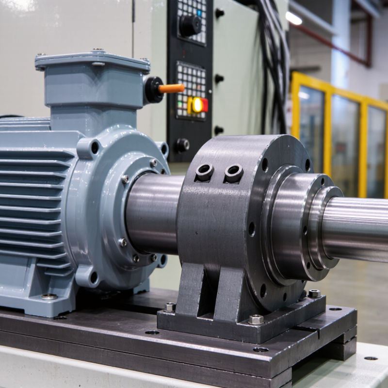
Start at the load. Record required torque, speed range, acceleration, and duty cycle before comparing direct drive motors. A motor that meets peak torque may still overheat during repeated starts or sustained low-speed operation. Include the driven load’s inertia and any shock loads; these are easy to overlook.
The U.S. Department of Energy’s 2014 U.S. Industrial and Commercial Motor System Market Assessment Report estimated that motor-driven systems account for about 68% of electricity use in U.S. manufacturing. That figure makes operating hours and load profile practical selection inputs, not just engineering details. Estimate annual run time and note whether the process runs continuously, in batches, or with frequent stops. Even a rough log is better than a guess.
Dust matters. Check ambient temperature, humidity, washdown exposure, vibration, and nearby corrosive substances at the actual mounting point. IEC 60529 IP ratings describe protection against dust and water ingress, but they do not establish resistance to every chemical or cleaning agent. Specify the enclosure and cooling method for real site conditions, and confirm allowable temperature limits with the motor supplier’s technical documentation. A site survey can miss seasonal heat or occasional spray; revisit assumptions before purchase.
Illustrative example: Ambient temperature readings at three possible installation locations. Actual conditions vary; measure the intended site and check that the motor’s temperature, dust, moisture, and vibration ratings suit the application.
Choosing a direct drive motor starts with the load, not the motor’s advertised peak torque. Estimate the torque needed to overcome friction, gravity, and acceleration. A rotating table carrying uneven parts may need much more torque during startup than at steady speed. Check continuous torque for normal operation and peak torque for short bursts. That distinction matters.
Next, match the required speed to the motor’s torque-speed curve. A motor may reach a high speed without a load, yet slow down when asked to turn a heavy assembly. Include the actual payload, shaft, and fixtures in your estimate. Their inertia affects acceleration and stopping distance. Check the full duty cycle, too. Repeated starts can create heat even when each movement is brief.
Leave a reasonable margin, but avoid choosing an oversized motor by default. Extra capacity can increase cost and may make motion harder to control. The right margin depends on changing loads, friction, and operating conditions; there is no single percentage for every machine. Calculations are a useful starting point, not proof. I would verify torque and temperature under a representative load, then revisit the assumptions if the motor runs hotter or responds more slowly than expected. A small test can reveal what a neat spreadsheet misses.
Compare motor architecture before comparing headline torque. Radial-flux motors are common and often straightforward to package. Axial-flux designs can offer a short, flat form, but their cooling paths and mechanical support need careful review. Iron-core designs can deliver strong torque density; ironless designs reduce cogging, though they may demand more current. A spec-sheet comparison can mislead. Check continuous torque, not just peak torque, and ask how each rating was tested.
Materials shape both performance and heat flow. Copper windings conduct electricity well, but winding layout affects resistance and hotspot formation. Laminated electrical steel helps limit core losses; permanent magnets can raise torque density, but temperature limits matter. The IEA’s Energy-Efficient End-Use Equipment report estimates that motor-driven systems consume about 45% of global electricity. That figure covers many motor types, not direct-drive units alone, but it shows why efficiency deserves scrutiny.
Cooling changes the practical operating envelope. Forced air is simpler, yet dust and restricted airflow can undermine it. Liquid cooling can remove heat effectively near the stator, but adds hoses, seals, and maintenance points. Ask for winding-temperature data under your actual speed and load cycle. Small detail. Also compare noise, service access, and sensor placement. I would not choose a design from efficiency figures alone; real installations rarely match a clean laboratory setup.
| Tip | What to Compare | Practical Selection Guidance | Trade-Offs and Checks |
|---|---|---|---|
| 1. Start with the load and motion profile | Required continuous torque, peak torque, speed range, acceleration, duty cycle, and load inertia. | Use the actual motion profile to determine RMS torque and peak demand. For rotating systems, power and torque are related by P = T × ω; low-speed applications can require substantial torque even when power is modest. | Peak torque is generally available only for a limited time. Confirm the motor’s continuous rating, peak duration, and thermal limits rather than sizing from peak torque alone. |
| 2. Compare motor construction | Radial-flux versus axial-flux geometry; iron-core versus slotless or air-core winding designs. | Radial-flux motors are widely used and offer many mounting options. Axial-flux designs can provide a short axial package. Iron-core designs can deliver high torque density; slotless or air-core designs avoid cogging associated with toothed iron stators. | Geometry alone does not determine performance. Compare torque at the required speed, package size, cogging or torque ripple, heat path, and the manufacturer’s test conditions. |
| 3. Match the feedback system to positioning needs | Encoder or resolver type, resolution, accuracy, commutation feedback, and environmental suitability. | Choose feedback based on the required positioning and speed-control performance. Verify that the drive can read the feedback device and supports the motor’s commutation method. | Encoder resolution is not the same as system accuracy. Mechanical alignment, control tuning, backlash elsewhere in the system, and temperature can also affect positioning results. |
| 4. Review materials and temperature limits | Copper windings, laminated electrical-steel cores, permanent magnets where used, and housing material. | Copper windings conduct current and generate heat through electrical losses. Laminated electrical steel helps limit eddy-current losses in changing magnetic fields. Aluminum housings can conduct heat effectively while keeping mass relatively low. | Check winding insulation class and the permitted operating temperature. For permanent-magnet motors, confirm magnet temperature limits and resistance to demagnetization under the intended current and thermal conditions. |
| 5. Choose a cooling method for the real duty cycle | Natural convection, forced-air cooling, or liquid cooling through a jacket or cooling passages. | Natural convection is simple and needs no fan or coolant circuit. Forced air can improve heat removal where airflow is available. Liquid cooling can support higher heat removal in a properly designed system. | Cooling performance depends on ambient temperature, airflow or coolant flow, installation, and heat-transfer surfaces. Include fan or pump requirements, maintenance, leak risk, and the cooling conditions used for published ratings. |
| 6. Check mechanical fit, inertia, and bearings | Rotor inertia, shaft or hollow-bore dimensions, mounting pattern, air gap, bearing arrangement, and allowable external loads. | Compare rotor inertia with the driven load when estimating acceleration and control response. Confirm that the motor’s mounting and shaft arrangement fit the machine without adding unnecessary couplings or transmission stages. | Direct drive removes a gearbox or belt only when the motor can meet the load requirements directly. Check allowable radial and axial loads, alignment tolerances, and the support needed for the driven mechanism. |
| 7. Verify ratings and operating environment | Torque-speed data, continuous and peak ratings, thermal conditions, ingress protection, contamination, and maintenance requirements. | Request torque-speed curves and rating conditions that match the intended installation. Check ambient temperature, dust or moisture exposure, vibration, and whether the motor needs a separate brake or protective enclosure. | Ratings from different designs are comparable only when test conditions and duty assumptions are similar. Validate the selected motor with the actual drive, mounting, cooling arrangement, and motion profile. |
A direct-drive motor removes the gearbox, but it does not remove integration work. Check whether the motor’s encoder or resolver matches the drive’s feedback interface, supply voltage, and supported communication protocol. Confirm required position resolution and update rate, too. A fine encoder cannot fix a controller that reads it too slowly.
Control the whole system. Compare continuous and peak torque with the real load profile, including brief acceleration peaks. Check moving-load inertia, current limits, and thermal conditions; a motor that meets the torque number may still overheat during repeated cycles. The U.S. Department of Energy’s Improving Motor and Drive System Performance: A Sourcebook for Industry reports that motor-driven systems account for about 70% of industrial electricity use. Efficiency matters. But sizing only for efficiency can miss dynamic demands.
Also verify mounting dimensions, shaft or rotor interface, cable routing, and available space around the motor. The International Energy Agency’s 2011 report Energy-Efficiency Policy Opportunities for Electric Motor-Driven Systems estimates motor systems use roughly 45% of global electricity. These figures describe the wider opportunity, not the savings from one motor. A compatibility checklist is less exciting than a torque curve, yet it can expose costly mismatches early. And leave room for doubt: supplier ratings may use different test conditions, so ask for the underlying curves and limits.
A direct-drive motor can remove a gearbox, but fewer parts do not guarantee higher reliability. Check the actual duty cycle, peak torque, speed range, heat, dust, and vibration. The U.S. Department of Energy’s 2014 motor-systems sourcebook reports that motor-driven systems use about 54% of U.S. manufacturing electricity. That makes operating efficiency a major ownership factor, not a minor specification. Small losses add up.
Ask suppliers for documented bearing life, encoder protection, cooling requirements, and service intervals under conditions like yours. Inspect how technicians will access the motor in your machine; a sealed unit may still need specialized service. I would not treat “gearless” as maintenance-free. That assumption is easy to make, and costly to test. Track unplanned stops, too, since a short repair can disrupt an entire production shift.
Compare total cost of ownership across the same service life: purchase and installation, electricity, maintenance labor, spare parts, downtime, and replacement. The DOE’s 2002 U.S. Industrial Electric Motor Systems Market Opportunities Assessment estimated that motor systems consumed about 63% of industrial electricity. Its scope differs from the 2014 manufacturing figure, so do not compare them as a trend. Use your own annual operating hours and electricity tariff to model costs. Then test the result against a realistic maintenance schedule—not an optimistic one.
Record required torque, speed, acceleration, and duty cycle. Include load inertia and possible shock loads. A motor that handles peak torque may still overheat during repeated starts.
Note annual run time and whether the process runs continuously, in batches, or with frequent stops. Even a rough operating log is better than a guess.
Account for friction, gravity, and acceleration. An unevenly loaded rotating table may need more torque at startup than during steady operation. That difference matters.
Continuous torque supports normal operation over time. Peak torque covers short bursts, such as starting or accelerating a load. Check both against the machine’s actual duty cycle.
Review the torque-speed curve under the real payload. A motor may reach its listed speed unloaded, then slow with a heavy assembly. Include shafts and fixtures in the load estimate.
The load’s inertia affects how quickly it accelerates and stops. It can be easy to overlook a heavy fixture or uneven payload. I might miss one during an early estimate.
Check temperature, humidity, dust, washdown, vibration, and nearby corrosive substances at the mounting point. Dust matters. Confirm enclosure and cooling requirements for those conditions.
No. IEC 60529 IP ratings describe protection against dust and water ingress, not every chemical or cleaning agent. Verify material and temperature limits in the supplier’s technical documentation.
Leave a reasonable margin for changing loads and operating conditions, but do not oversize by default. Extra capacity can raise cost and make motion harder to control. Test torque and temperature under a representative load.
Choosing a Direct Drive Motor begins with a clear understanding of the application and operating environment. Consider the machine’s duty cycle, available space, temperature, exposure to dust or moisture, and the precision required. Then match the motor’s torque and speed capabilities to the load, including start-up demands, acceleration, and expected changes in operating conditions. Selecting a suitable design, construction materials, and cooling method can help the motor perform consistently in its intended setting.
Next, check that the motor’s feedback devices and controls work with the rest of the system. Review how it will be installed, monitored, and maintained, and consider reliability alongside purchase and operating costs. Comparing expected service needs, energy use, and system integration requirements helps reveal the total cost of ownership. By evaluating these factors together, you can choose a motor that fits both the technical demands of the application and its long-term operating goals.

AxisPro Motor